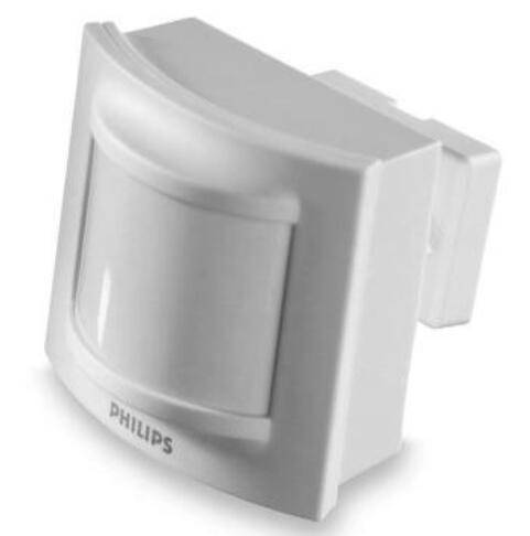
DUS30-LHB-DALI
Features
• Communication with Philips DALI MultiMaster controllers – The
sensor can be used as part of a net control system in conjunction
with timer clock schedules, head end software, and daylight
harvesting sensors. It enables control over multiple lighting groups
connected to the lighting control system
• DALI bus powering – This removes the need for additional power
supplies
• Powerful internal programmable logic controller (PLC) – Custom
scripts can be written to provide process control based on conditional
logic.
• Simple installation – The sensor is supplied with a wall mounting
block that allows the sensor to be mounted and locked into position.
When installing onto a Philips TTX400 trunking lighting-line system,
use an additional ZTX400MB-MDU mounting bracket.
Installation steps
Power down and isolate the DALI bus before wiring the device. Always treat the DALI bus as live. The DALI bus is not touch safe unless de-energized.
Follow the recommended number of sensors per DALI bus as the Philips load controller installation manual
The device must be installed at least 2 m away from radio devices, such as Wi-Fi routers.
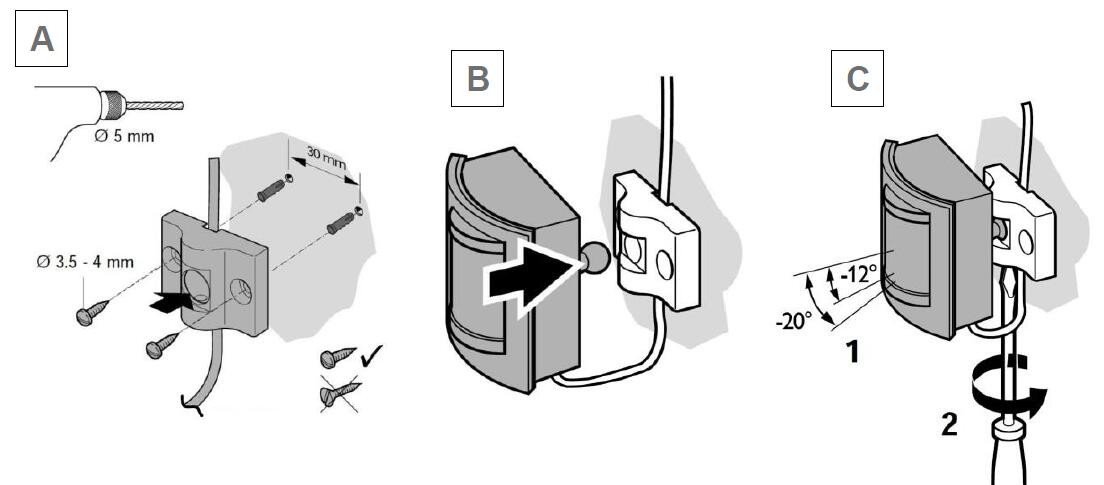
Wall mounting
Refer to diagrams A, B, and C.
1. Drill holes to line up with the mounting block. Use brick plugs if mounting the device onto a brick wall.(A)
2. Run the fly lead of the sensor behind the mounting block.
3. Once the DALI bus cable is positioned behind mounting block, secure the mounting block by hand by screwing it tightly to wall.
4. Push the sensor into place and adjust it into position where motion detection is required.
5. Fix the locking screw below the mounting block to hold the sensor in position.
6. Terminate the sensors fly leads to the DALI bus ensuring that the connection is secure, correctly insulated, and isolated.
7. The unit configuration can only be performed by commissioning software EP. No mechanical settings are available.
Product specifications
DALI network supply: 9.5 – 22.5 V DC 9mA
DALI insulation system: Basic
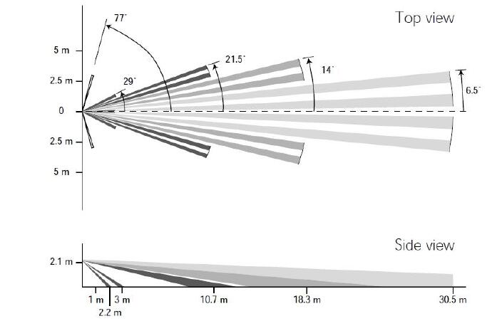
Motion detection range: 15 m
Detection zones: 30° wide lens with 14 beams in 4 detection layer. Long range, narrow angle corridor pattern. Maximum coverage is 3 x 25m
PE cell: Range 5 lux to 10,000 lux (illumination of non-reflective surfaces in sensor’s field of view) IR receive: Philips RC5 codes for network sign on only. 12 m max range
Controls: LED indicator for walk test, IR receive and network sign-on button.
Connection: 30 cm fly lead
Control bus: DALI bus from Philips DALI MultiMaster Controllers only
Compliance: CE, C-Tick
Operating temperature: -5° to 50°C ambient temperature, 0% to 90% RH non condensing
Storage and transport: -25° to 60°C ambient temperature, 0% to 90% RH non condensing
Construction: Polycarbonate white (RAL9010) IP20, UL94-V0 rated
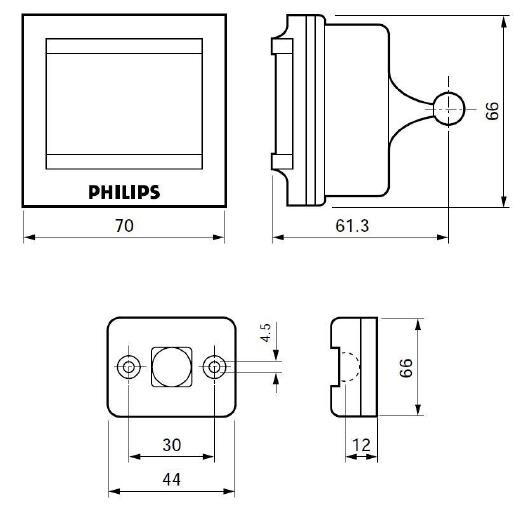
Dimensions: H 66 mm x W 70 mm x D 61 mm
Packed weight: 116 g
|


